
Use Cases & Use Case Diagrams captures the interactions between stakeholders of a System of Interest about its behavior.
Use Cases & Use Case Diagrams describes the system’s behavior under various conditions, initiated by the primary and secondary stakeholder upon the system of interest.
- Primary Actor initiates interactions with the system of interest.
- Secondary Actor initiates interactions with the system of interest.
- Stakeholder is someone or something with a vested interest in the behavior of the system of interest.
Key Elements of Use Cases and Use Case Diagrams
On a Use Case Diagram, the primary elements that are leveraged are Actors, Blocks, or Use Case Objects. Understanding when and where to use each of these elements is key for developing comprehensive use case diagrams.

Actor
An actor represents someone or something that has an external interface with your system. The name of an actor conveys a role played by a person, an organization, or another system when it interacts with your system.
Use Case
Describes the expected functionality of a system.
Block
A Block is a modular unit that describes the structure of a system or element. It may include both structural and behavioral features, such as properties and operations, that represent the state of the system and behavior that the system may exhibit.
Key Relationships of Use Cases and Use Case Diagrams
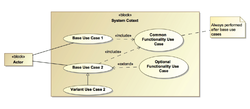
On a Use Case Diagram, Actors may interact directly or indirectly with the system of interest. The relationships created between actors and use cases represent the communication that occur. There are 4 main relationships that can be used within these diagrams:
Generalization
A generalization relationship provides a mechanism to specify variants of the base use case.

Communication
A communication path represents an association between two Deployment Targets. It connects actors to use cases.
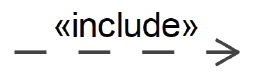
Include
An include relationship provides a mechanism for factoring out a common functionality that is shared among multiple use cases and is always performed as part of the base use case.
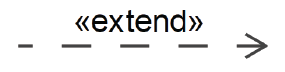
Extend
An extend relationship provides an optional functionality, which extends the base use case at defined extension points under specified conditions.
Best Practices
The use of Blocks over Actors to represent external users allow more traceability through its attributes than actors. If the traceability to the impacted attributes are not desired, the utilization of actors is preferred.
The use of System Context Blocks over Packages to show the environment in which Use Cases constrained within. This is an optional step being that some systems architecturally are not flushed out in it entirety and system context is unattainable. But when available, the more context you can add to these diagrams, the better.
Use Cases should contain a VERB. Far too often use cases read as system functions. There is a big difference ‘Initiate the System” and “System Power On”. Always think of a system behavior being initiated by an action or an occurrence.
Use cases are meant to be formulated through interviews with stakeholders and design agents. Think of the formed narrative as almost a sheet of ideas where you can come up with the best use case name with the functions it owns.
Capturing how stakeholders interact with the system of interest will help identify external interfaces.
Use Cases are used to identify and capture System Functionality.
Pingback: What Are Use Cases? - Beyond MBSE
Pingback: Creating Use Case Roles - Beyond MBSE
Pingback: Actor - Beyond MBSE