
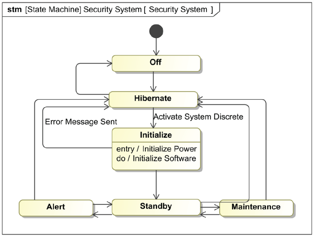
State Machine diagrams represent the behavior(s) of entities capable of dynamic behavior by specifying their response to the receipt of event instances.
State Machine Diagrams are part of the family of behavioral diagrams and serve a unique purpose of showing the sequence of states of an element and what triggers (Events) force movement from one to another.
The triggers and entrance and exit criteria are some of the most fascinating things about these diagrams.
State Machine Diagrams: Key Elements
The state machine represents behavior as the state history of an object in terms of its transitions and states. The activities that are invoked during the transition, entry, and exit of the states are specified along with the associated event and guard conditions.

State
A State declares a significant condition in the life of a SysML Block within its State Machine.
Initial
An Initial node declares the starting state of the State Machine.


Final
A Final node declares the ending state of the State Machine, and its completion.
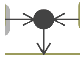
Choice
A Choice node declares a Junction with a mandatory ‘else‘ transition.

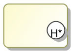
History
A History represents the last active State of the State Machine prior to its interruption.
Junction
A Junction declares a decision point at which a Transition branches out into multiple guarded, alternative paths.

Entry
An Entry node declares an Entry point between State Machines, Substate Machines and Regions.
Exit
An Exit node declares an Exit point between State Machines, Substate Machines and Regions.


Terminate
A Terminate node declares a termination State in which the State Machine no longer operates.
State Machine Diagrams
State Machine Diagrams: Key Relationships
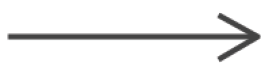
Transition
The Transition relationship is created between two states. The transition specifies event occurrences and guard conditions. Transitions take one state configuration to another.
Best Practices
The level of hierarchy at which state machine diagrams should be made is really something that should be well thought-out by the system designers. Does it make sense to do an overall system state machine diagram? Not always due to the complexities of the subsystem or components that are part of the given system? For Example, if you have an overall system states of ‘Standby’ and ‘Operational’ within your system, is there ever an instance where one component within the system could be in standby and another be operational. This is VERY common in systems where components sit in standby states until commanded otherwise. It might make sense in a lot of cases to do subsystem state diagrams to simplify things.
Remember to always consider complexity and if stakeholders are interested in what drives a system to change states.
This likely should occur after quite a bit of behavior modeling, use cases and their specifications.
Behavior Transitions
State Machines are often thought of a way to illustrate Use Case Scenarios.
States vs. Modes
A change in State happens from outside the System.
A change in Mode happens from within the System.