
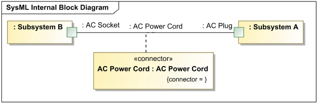
Internal Block Diagrams can help define the interface and characteristics of a system, as well as detail the communication between system elements.
Often Internal Block Diagrams are perceived as a comprehensive diagram to show how a system will always be interconnected. This is not always the case. You cannot expect a static Internal Block Diagram, to capture all the communication and interconnections of a dynamic system.
Since Internal Block Diagrams are the only diagrams in your systems model that hinges on the context of the diagram, an internal block diagram must describe everything internally of the selected point of interest. If your selected point of interest is a subsystem, then only things within the subsystem should/can be portrayed. Anything external to that subsystem would either be a reference part or would not be shown.
Internal Block Diagrams: Key Elements
On an interface diagram, some of the primary elements that are leveraged are the part properties reflecting the class objects that they represent.

Part Property
A Part Property is a property that specifies a part with strong ownership and coincidental lifetime of its containing Block. A local usage or a role of the typing Block in the context of the containing Block is described by a part property.
Reference Property
A Reference Property is a property that specifies a reference of its containing Block to another Block.

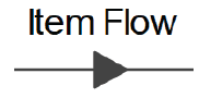
Item Flow
An Item Flow indicates the flow of items via a Connector or an Association.
Internal Block Diagrams
Internal Block Diagrams: Key Relationships
The relationships identified in these diagrams are fundamental for understanding the interactions between system elements. Typically IBD’s are often leveraged for defining interfaces, so it is important to clearly show and identify the captured interfaces.
Full Port
A Full Port is a port which is considered as a separated element of owning Blocks.


Proxy Port
A Proxy Port is a port that specifies features of owning Blocks or Part Properties so that they are available to external blocks through external ports.
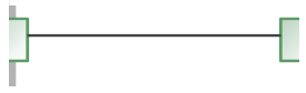
Connector
A Connector is used to depict the interconnection between part properties or ports.
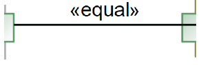
Binding Connector
A Binding Connector is used to specify that the interfaces at both ends are equivalent.
Internal Block Diagrams
Key Facts and Highlights
Ports or No Ports, That is the Question
Is it important to show ports on every interface diagram or only on some or none at all? If you can convey everything without ports and it meet your customer’s needs, then don’t show them. Ports are important for detailing the interface specifications of your system. If you are not developing or detailing an interface specification i would argue that ports are not required for you to put them on interface diagrams.
Property Flows on Diagrams
Is it important to show the flow of matter throughout your system? If so, does it need be shown holistically? Also does the flow of matter in your system alter at different stages? If the flow of matter does not need to be shown then life is relatively simple.
The flow of matter differs as the behavior of the system changes. Because of this, it would not be accurate to show the flow of all the matter within your system at one time, multiple diagrams should be leveraged.
Interface Specification
If capturing how interfaces of your system should be developed is important, then creating holistic system element interface diagrams should be considered. These diagrams have a central system element as the focus of the diagram and other interfacing system elements are identified. On these diagrams the flow of matter is shown and specified, enabling a design agent adequate information to develop the system elements interfaces.
Property Flows on Diagrams
It is important to keep a consistent perspective. A common method to keeping a consistent perspective for interface diagrams is by portraying common hierarchy levels. Since, your system architecture is segmented, only one hierarchy level should only be portrayed on an interface diagram.
Pingback: Blocks and Block Definition Diagrams - Beyond MBSE
Pingback: Block - Beyond MBSE